The VFD layer clock kits are sold out! If you want to get your hands on one, you will have to use this open source design to make your own.
If you’re looking for assembly instructions for your clock kit, head over to the VFD layer clock assembly page.

If you’ve ever gone looking for a nixie or vacuum florescent display clock on the internet, you’ve probably noticed that the number of pictures of these unique clocks far outnumbers the number of actual clocks and open source designs that are available. This clock is designed to change that with an open source design that is compatible with a wide variety of vintage and modern displays including vacuum florescent display tubes and modern LED displays.
The layer clock starts with a 4 digit binary coded decimal clock that keeps the time and outputs a versatile 4 digit binary coded decimal format that is compatible with just about any display, including IV-6 and IV-3 VFD tubes, seven segment LED displays and 4 bit Binary Coded Decimal (BCD) 5mm LED displays.
Open Source
The open source documentation for the Layer Clock is below. It has been organized by layer. Each layer has four files: a schematic in .PNG format for easy viewing, a .JSON file for the schematic and the PCB that can be imported into Easy EDA, as well as a bill of materials. Gerber files are not included, because you can’t import them and modify them. You can generate your own gerber using .json files.
Updated on 11/18/2022
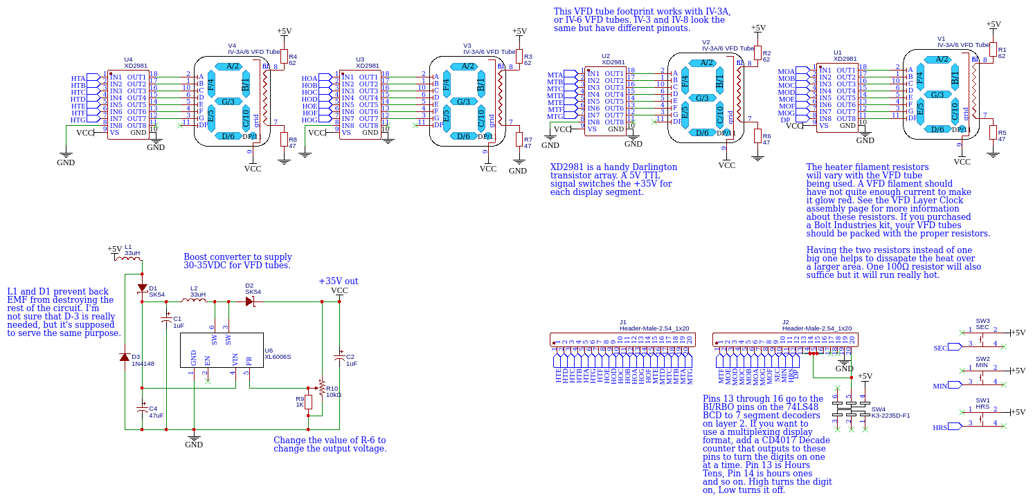
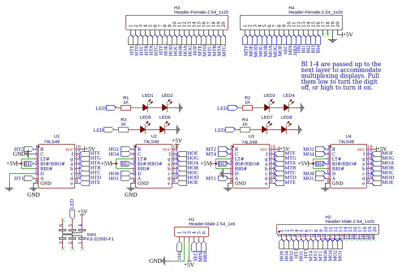
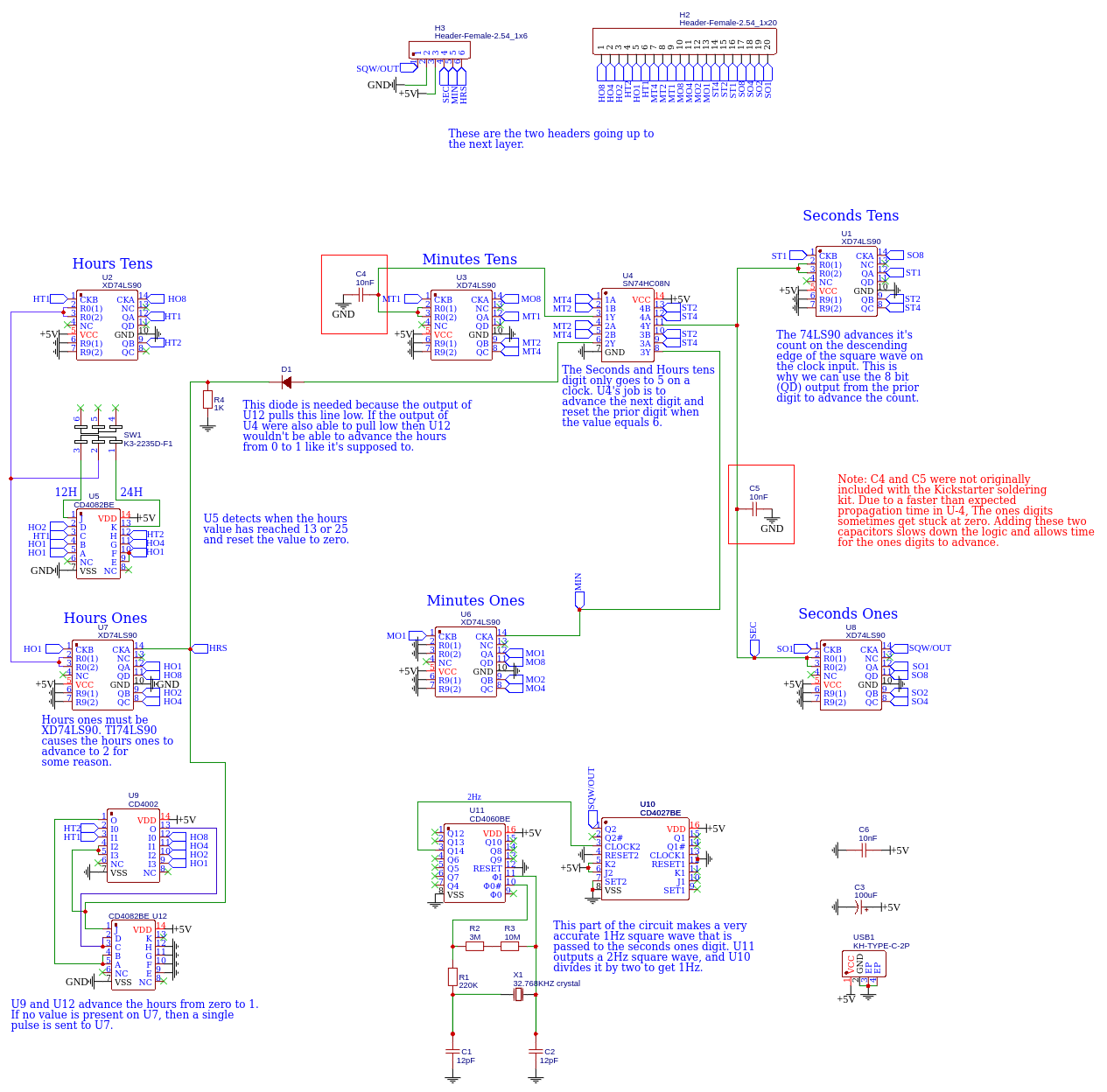
The middle BCD to 7 segment converter layer and the VFD layer have been updated to allow the use of a multiplexing display. See VFD layer’s schematics for details. Two .01μF capacitors have also been added to the BCD clock layer to prevent the ones digits from getting stuck at zero.
Creative Commons License
The Bolt Industries Layer clock is open sourced under the Creative Commons license. You are free to download the following files and modify them to your liking for your own personal use, but they may not be used for commercial purposes.
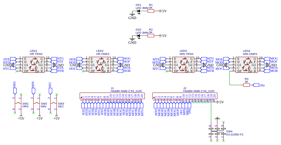
Layer 3: 7 Segment Display Formats
7 segment LED display
A 7 segment LED display is pretty straightforward.


Vacuum Fluorescent Display Layer
This design is compatible with IV-6 and IV-3A VFD tubes. An XLSEMI boost converter provides the roughly 30 volts required for the VFD tubes. A P channel XD2981 8 Darlington IC switches each high voltage segment.


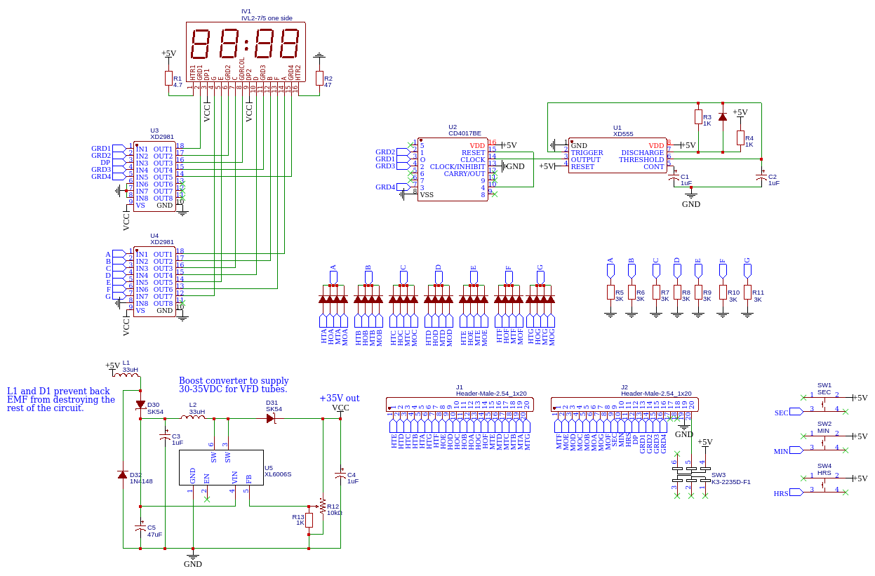
IVL2-7/5 Vacuum Florescent Display Layer
Another display option is the IVL2-7/5 VFD display.

The IVL2-7/5 VFD is an ideal choice because it’s got 4 digits. It’s square form factor is not the most attractive, but if you look closely at it’s grid wires and it’s digits it’s pretty darn cool.Another display option is the IVL2-7/5 VFD display. The IVL2-7/5 VFD is an ideal choice because it’s got 4 digits. It’s square form factor is not the most attractive, but if you look closely at it’s grid wires and it’s digits it’s pretty darn cool. This is a multiplexed display. This means each digit must be turned on and off one at a time. This is accomplished with the use of a 555 timer and a 4017 decade counter. The 555 timer cycles through each digit at about 600Hz. The outputs of the 4017 decade counter turn the digits on and off, and they also go down to layer two where they enable each of the 7 segment decoders one at a time.
The design requires a lot of switching diodes. It’s already a very dense PCB, so I used really small surface mount diodes. I don’t recommend trying to hand solder these.
Layer 2: 4 Bit Binary Coded Decimal to 7 Segment Converter or BCD display
Binary Coded Decimal to 7 segment decoder
This layer converts the 4 bit binary coded decimal from the lower layer to a human readable 7 segment format.


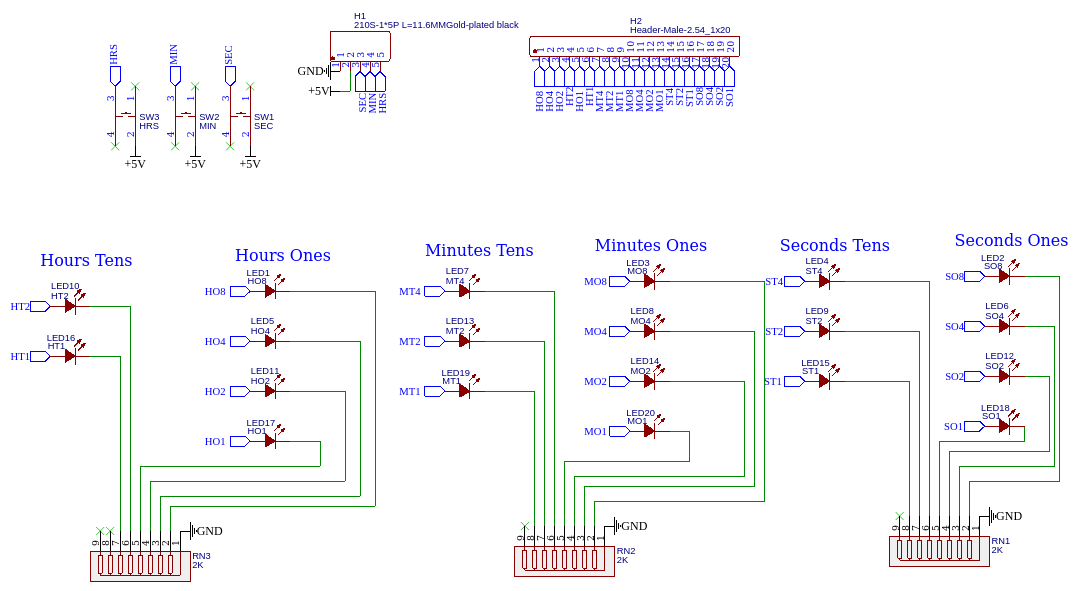
Binary Coded Decimal 5mm LED Display
This layer just displays the time as a 4 bit binary coded decimal. To read the time, the digits in each collum must be added together. The time shown in the picture below is 12:57:23.


Hewlett Packard HDSP display
Hewlett Packard’s HDSP displays are a perfect candidate for this application. Any 8 pin DIP HDSP display should work.


Layer 1: Binary Coded Decimal Clock
This layer keeps the time and outputs a 4 bit binary coded decimal for each digit of the clock. There are two ways to do this: a TTL clock built with integrated circuits, or a Raspberry Pi Pico software based clock.
Option one: TTL BCD Clock with 7400 and 4000 series Integrated Circuits


Updated design with USB-C
Original design:
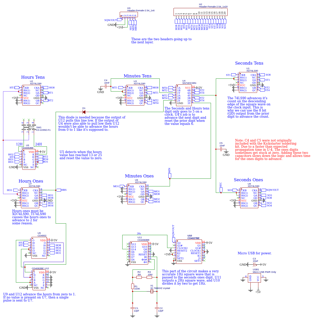
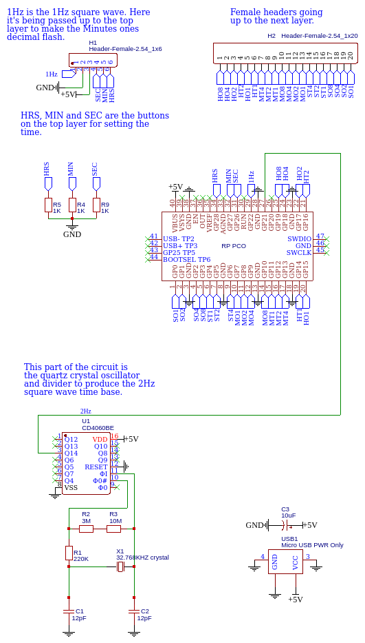
Option 2: A software based Raspberry Pi Pico clock.
This layer does exactly the same function as the TTL BCD clock, but with software.


Firmware
Layer 0: Bottom Cover Plate
The last layer is simply a bottom cover plate. Also the clock requires some hardware to put it together. You will need: 8 M3 x 11mm brass standoffs, 4 m3 dome nuts, 4 m3 x 10mm screws and 4 m3 nuts. some rubber feet are a good idea also.