If you’re looking for the open source design files, then scroll to the bottom of the page. If You’ve purchased a kit and you’re looking for assembly instructions or troubleshooting help, then read on.
The clock doesn’t have to be assembled in a particular order, as long as everything ends up in the correct place. I recommend starting with the smallest components and moving up to the larger components because it’s easier to keep everything flat against the PCB while you’re soldering. I like to start with the Zener diodes, then the switching diodes, the resistors, the IC’s, and the LED’s last. one important thing to note is that the crystal must be glued to the PCB with a tiny drop of super glue in order to allow it to resonate accurately. If it’s left to float in the air, the clock won’t keep time accurately.
Here’s a few other things to take into account:
There are two 3.9V Zener diodes, and a handful of 1n4148 switching diodes. The two types of diodes look nearly identical, so be careful not to mix them up! The Zener diodes are labeled on the board with ZD1 and ZD2, while the others are labeled D1, D2 etc.
Be careful of the orientation of the IC’s, diodes, LED’s, and electrolytic capacitors. The polarity of the rest of the components does not matter.
The IC’s are sensitive to static electricity, so be careful not to zap them.
Once you’ve got everything soldered together, screw on the back cover plate and you’re done!
If you need to 3d print a base:
My web hosting service doesn’t like .STL’s for some reason. You can find it on Thingiverse here: https://www.thingiverse.com/thing:4925845
How to set the time:
When you first power the clock up, sometimes more than 1 number in each digit will be lit. Just cycle through each digit to clear them out.
Setting the time works best if you start with the hours, then minutes and seconds last. The seconds button doesn’t advance the seconds, but rather resets them to zero. The 4017’s are very sensitive to every button press and the buttons tend to be “bouncy.” I’ve added pulldown resistors and debounce capacitors to compensate for the bounce. This helps a lot but it isn’t quite perfect so it may take several tries to get the correct time.
The hours 10’s only displays two digits. It’s possible that the count will start at some value greater than zero when the clock is powered on. To fix this, just advance through the digits until the 1 LED turns on.
Enjoy!
If you purchased the printed graphic circuit board:
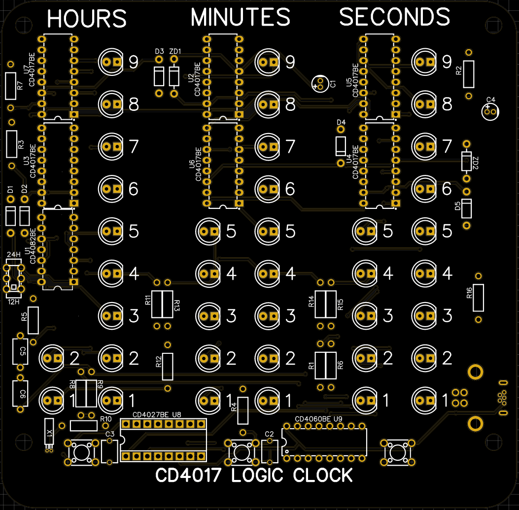
Here is the silkscreen layer that’s covered up. Follow this to see where to place each component. The graphic is printed directly over the top solder pads and the silkscreen because the artwork looks really nice this way. Try to only apply a minimal amount of heat to avoid burning the graphic on top of the solder pads.

Troubleshooting Guide
If you get the clock assembled and it doesn’t quite work correctly, try these steps.
- The clock doesn’t turn on: The USB jack is soldered onto the front side of the board. De-solder the jack and re solder it on the other side. Also check the orientation of the CD4017’s and the CD4082. The notches should all be pointing down.
- Two LED’s are dimly lit on one of the digits, and the segment won’t advance: One of the CD4017 decade counters is soldered in upside down. De-solder it and flip it around.
- The hours tens don’t light up: When the CD4017’s are powered up, the count will start at a random digit. The hours tens only go to 2 on a clock, so there’s no reason to display the rest of the digits. The count has probably started at a value higher than 2. Just advance the hours until the 1 LED lights.
- A whole bunch of digits are lit when the clock is turned on: These are garbage digits that happened to be ON when the 4017 powered up. Just advance the time until the extra digits clear.
- One of the LED’s doesn’t light up: Check for a solder bridge across the LED. Also check that the notched side of the LED is facing right.
- The clock is fast or slow: The 32.768Khz crystal needs to be glued to the PCB. If it’s not, it “sways” from side to side.
- The seconds don’t advance the minutes, or the minutes don’t advance the hours: One of the two 1uF electrolytic capacitors is installed backwards, or one of the two Zener diodes is backwards.
- One of the tens digits is blank: The count didn’t reset to zero after reaching 60, and instead it probably advanced to 6: One of the two 1uF electrolytic capacitors is installed backwards, or one of the two Zener diodes is backwards.
- The clock powers on, but the seconds don’t advance: Check for a solder bridge across the crystal oscillator. Also check that the two IC’s on the bottom of the board are properly installed in the correct orientation.
- The hours don’t reset to 1 after reaching 12 or 24: check to see that the CD4082 dual 4 input AND gate is installed in the correct orientation with the notch facing down.
- One of the columns of LED’s doesn’t light up: Check the 3K LED resistors for a cold solder joint

The open source design files are below. the files with the .Json extension can be imported into Easy EDA and modified to your liking.