Thank you for purchasing the Pico 87 mechanical keyboard! Here you will find assembly instructions, firmware and a troubleshooting guide.
Are you considering building your own keyboard? You can check out my how to guide in Hackspace Magazine: https://hackspace.raspberrypi.com/articles/how-i-made-a-pcb-mechanical-keyboard
If you’re looking for the open source hardware or firmware, head on over to the Bolt Industries GitHub repo. The firmware is also available below.

BMK firmware: Download and open in the Arduino IDE and follow directions in sketch.
BMK contains shortcut macros that work nicely with the shortcut legends on the available shortcut trim.
BMK Basic is a plain old keyboard with all the usual function keys and regular keyboard keys.
KMK firmware: Head over to the KMK GitHub repo for installation instructions and the rest of the firmware.
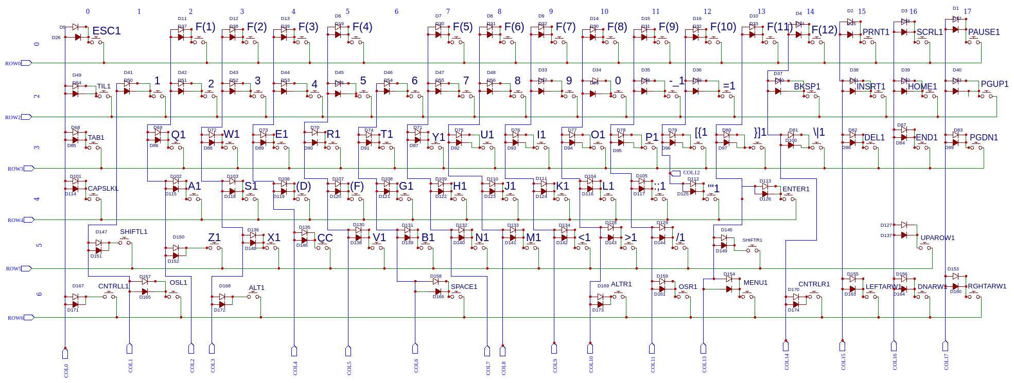
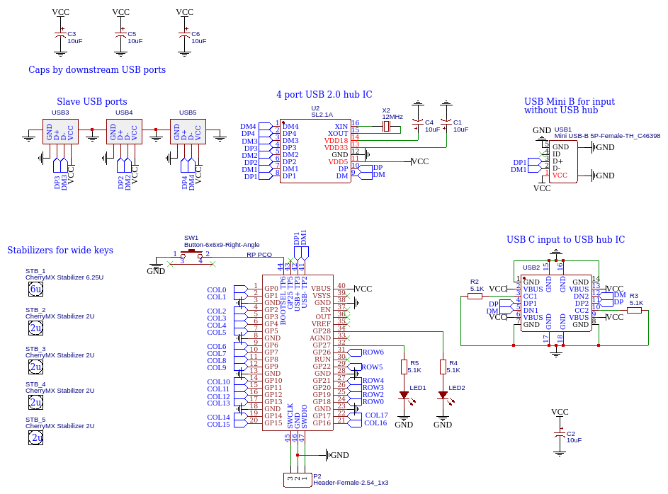
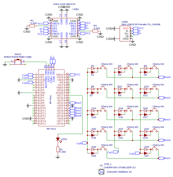
Schematic Diagrams: Matrix shows the keyboard matrix. Pico shows the portion of the circuit containing the Raspberry Pi Pico and USB hub. Previews in pictures below.
Assembling your keyboard/numerical keypad
You can assemble the keyboard in any order that you like, but this method the most efficient. The procedure is the same for both the numerical keypad and the keyboard.
Step 1: Start by soldering the smaller components and the Pico. It is a lot easier to do this before there’s other larger components interfering. Tip: place a peace of scotch tape on the main PCB under the Pico to allow a small air gap between the Pico and the PCB. This will make it a lot easier to get a good connection on the bottom solder pads. It is critical that the Pico is perfectly aligned inside of it’s box so that the bottom solder pads can make a good connection.


Step 2: Solder the smaller through hole components such as the capacitors, and diodes.
Note that when you solder the USB-C connector, some of the pins will try really hard to form a solder bridge. This is actually OK! The right picture is an enlarged view of the bottom of the connector. The left shows the traces on the PCB. I’ve circled the pins that tend to want to bridge. They connected together anyway. If one of the pins not circled is bridged to another pin this is a problem!


IMPORTANT:
Before proceeding to step 3 it’s a really good idea to upload the firmware and test the USB ports to make sure the USB is working. It’s really easy to end up with a cold connection on the bottom of the Raspberry Pi Pico, or on the USB hub IC. It’s easier to fix this before there’s other components in the way.

Step 3: Place all 87 key switches in their holes. You’re probably wandering how to turn the PCB over without dumping all the switches out. There’s a trick to help with this! Use some tape to attach the keyboard bottom PCB over the switches in such a way that all the switches are compressed in place. Compressing the switches while soldering forces them to all be pressed firmly into their holes. Once all of the switches are held down firmly, solder them in place.


Step 4: Separate the two PCB’s and remove any remaining tape. Place an m3 x 8mm bolt through each hole in the bottom PCB, pointing up from the bottom with an m3 nut on the top side. The Bolt Industries logo should be on the bottom.

Step 5: Add the stabilizers to the main PCB.
The metal bars all face down.
Step 6: place the main keyboard PCB on top of the bottom PCB and tighten a 10mm brass standoff on top of each bolt. The key to making the keyboard nice and rigid is to tighten each fastener nice and snug. Be careful not to over tighten them, the threads will strip.

Step 7: add the top trim and screw it in place with M3 x 8mm threaded fasteners. Alternatively you could add the key caps next. It’s a little bit easier to re arrange them without the top.

Step 8: place the key caps and flash the firmware! At this point you’re done. It’s not a bad idea to check that each key works properly. There’s a handy too to do this over at https://www.keyboardtester.com This nifty tool displays the key on the screen that’s been pressed, so you can see that each key works.


Troubleshooting Guide
If you get your keyboard put together and find that something doesn’t quite work take a look at this troubleshooting guide.
| USB issues | |
| The keyboard doesn’t work when connected via USB mini-B. | Check the alignment of the Raspberry Pi Pico. The most likely cause is a cold connection on the solder pads on the bottom of the Pico. Try heating them with a soldering iron for a while, and aggressively adding solder. If you have a needle point soldering iron try inserting it through the hole to where it can touch the bottom of the Pico. |
| *** | |
| The keyboard doesn’t work when connected via USB-C | Verify the Pico’s bottom solder pads as described above. This is the most likely cause. Also check the orientation of the USB hub IC. Give the USB-C connector another pass with the soldering iron in case there’s a cold connection hiding on it’s pins. Check for solder bridges on the USB-C connector and the USB hub IC. |
| *** | |
| My USB port still doesn’t work | Connect a micro USB cable directly to the Pico to see if you can reach it this way. If this works, there’s probably a cold connection on the bottom of the Pico. If this doesn’t work, then check for a solder bridge anywhere on the DC bus. Check the USB hub IC, the electrolytic capacitors, the Vbus terminal on the pico and all of the USB connectors. A solder bridge hiding in any of these places will cause the keyboard to short the upstream USB port and nothing will work. |
| Keyboard problems | |
| My Enter key sticks | The stabilizer from the Shift key is pressed against the Enter key stabilizer. Remove the Shift stabilizer and trim off a slight amount of plastic where the two stabilizers touch. This can be done with wire cutters or sandpaper. |
| *** | |
| My space bar sticks | Push the space bar from side to side while forcing it up and down. This will help break in the stabilizers. Also, try loosening the stabilizer screws about 1/8th of a turn so the stabilizers can wiggle. |
| *** | |
| I have a wiggly key | The switch isn’t quite all the way in the PCB. Take the top trim and bottom off of the keyboard and heat the wiggly key’s solder pads while pressing on the button. It will pop into place. A wide, blunt soldering iron tip works best for this. |
| *** | |
| One of my keys doesn’t work | check the solder pads on that switch, as well as the corresponding diode. Also try uploading the default firmware if you’ve made any changes to rule out a firmware issue. |
| *** | |
| My keyboard bows easily | Take the three layers apart and tighten all the threaded fasteners starting with the nuts and bolts on the bottom cover. |
| *** | |
| My Caps lock key doesn’t light up | check the orientation of the LED. |
| Firmware problems | |
| I don’t see the Pico USB drive when I connect the keyboard to my computer | Start with the USB troubleshooting steps above. If the USB functionality is working, try pressing down the Bootsel button on the top of the Pico with a thin object while plugging in the Pico to USB. If this works, then there’s most likeley a cold connection on the bottom of the Pico. Run a soldering iron over the larger solder pads on the bottom, and add more solder. Insert the tip of your soldering iron through the hole in the PCB until it touches the bottom of the Pico. |
| *** | |
| I loose connectivity to the USB devices that are plugged into the USB hub | For some reason this happens when uploading firmware from the Arduino IDE if you don’t un-plug the USB-C connector and hold down the Bootsel button while plugging in the USB cable prior to uploading the firmware. |
| *** | |
| Don’t see your problem listed? | Send an email to ian@boltind.com. I’m happy to help! |