

This design is now available as a soldering kit HERE. The kit includes everything you need except the HDSP displays. A 6 digit version is also avalable as an open source design and a soldering kit.
This design was updated on 4/21/2012. The revisions include more decoupling caps, power and ground planes, and a PWM dimming controller.
I developed this neat little clock that uses the HP HDSP “smart” LED display. These HDSP displays were largely what displaced Nixie tubes and VFD tubes. What makes them so cool is that they use a 4 bit binary coded decimal input, and an on board die converts the BCD to a seven segment display output. The best part is that you can easily see the die and it’s wire bonds through the glass!
This page is intended to be a guide to build your own HDSP clock. I will not be Kickstarting or selling this clock because the HP HDSP displays are oddly even harder to come by than Nixie or VFD tubes! You’re welcome to use my design however you like to make your own clock. The same circuit would also work very nicely with the ubiquitous TIL-311 “smart” display.
How It Works
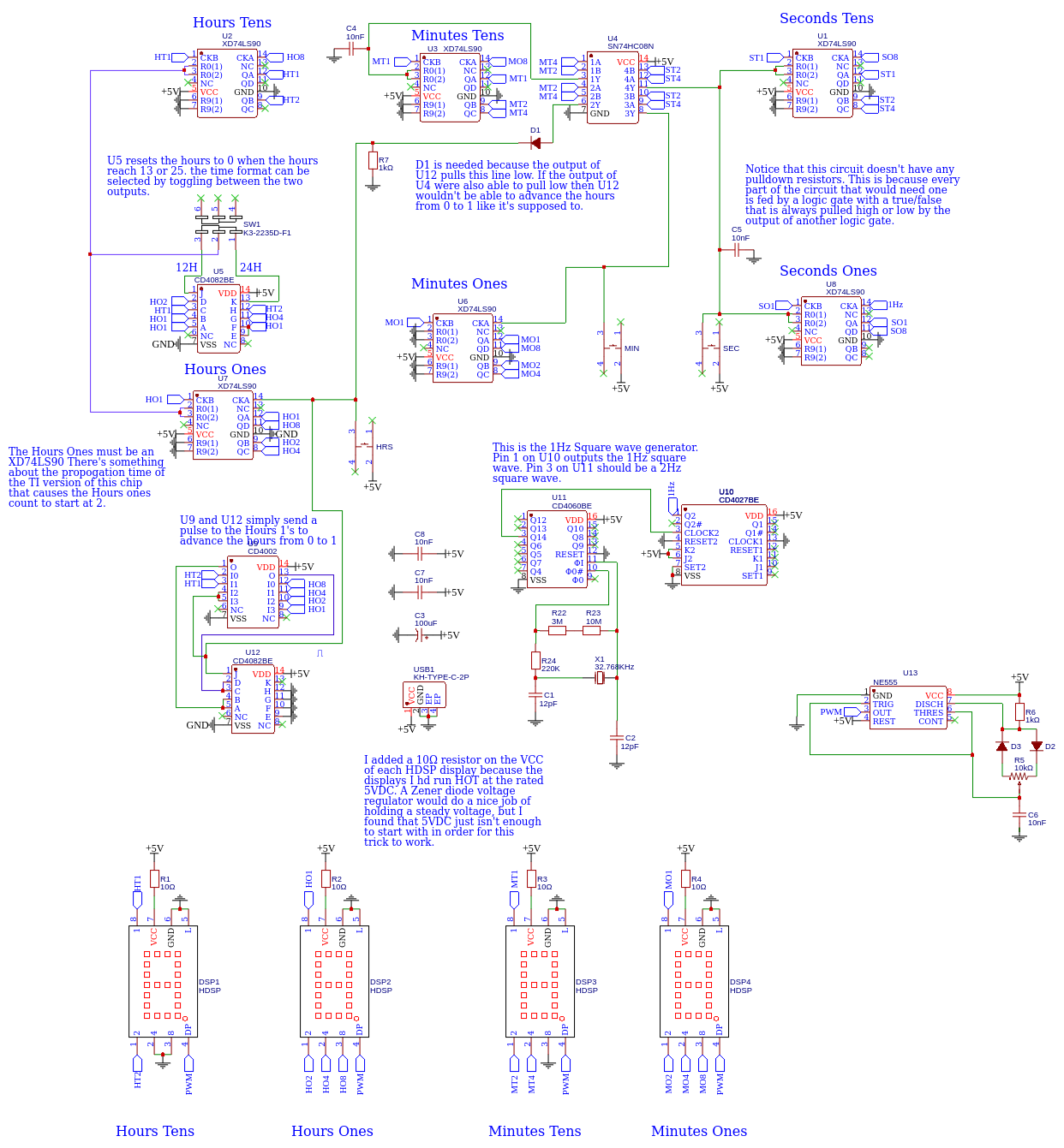
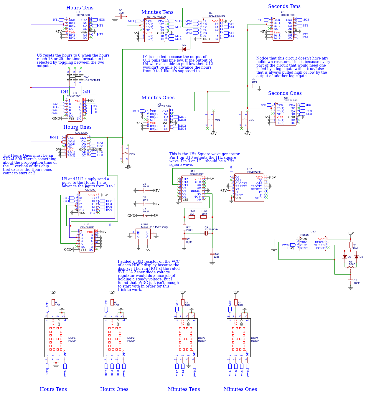
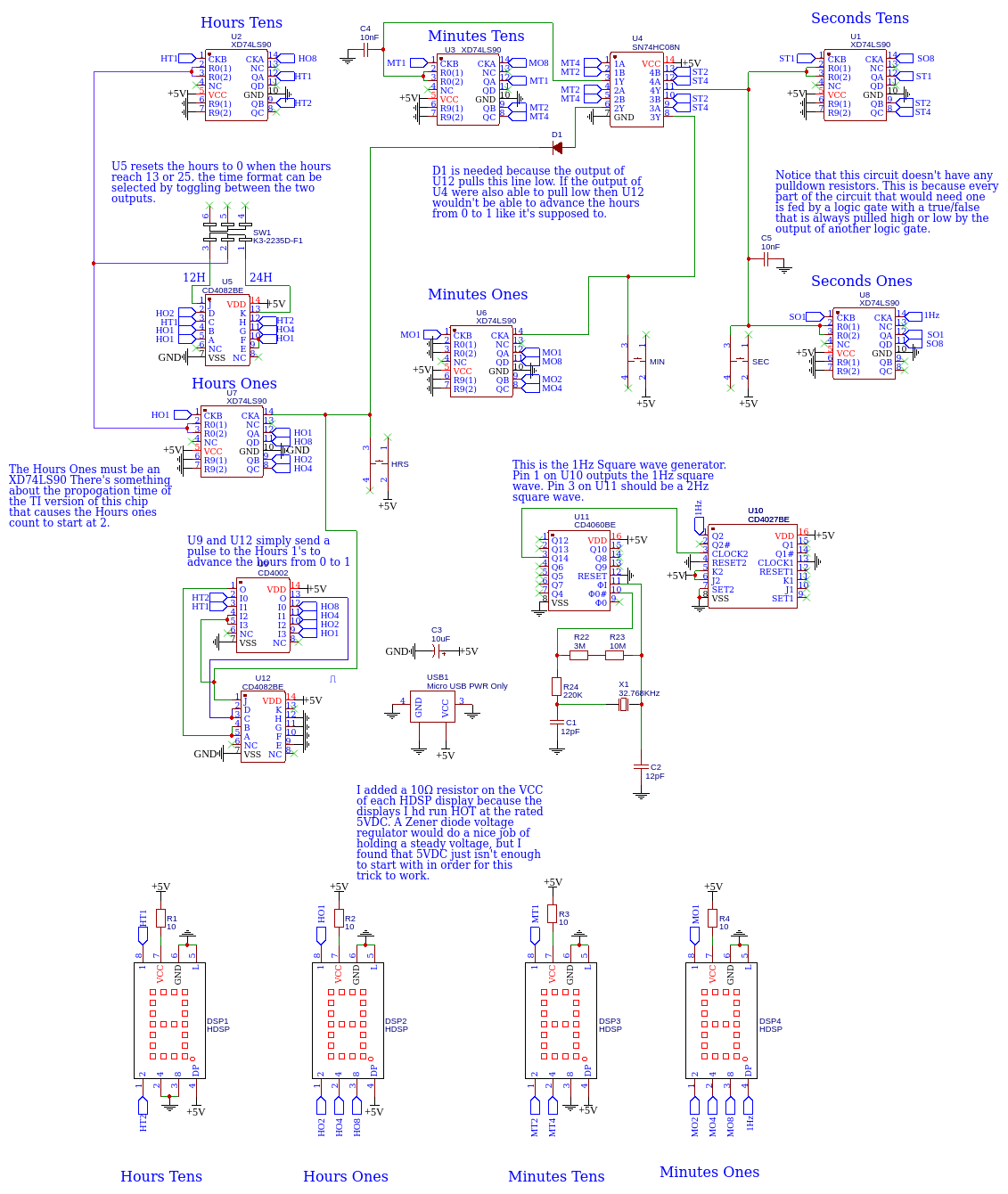
The clock itself is based on the XD74LS90 4 bit binary coded decimal counter by Xinluda. The Texas Instruments 74LS90 works too, however something is different about it’s propagation time and the hours tens do odd things when the count is 1 or 0. This could probably be resolved with a small capacitor on the Hours Tens clock line, but for me the easier solution was the Xinluda chip.
The crystal oscillator circuit is ubiquitous among all off my clocks. I prefer a crystal oscillator over using the power grid frequency. I am a power grid operator and I can tell you that the grid doesn’t keep time as well a some people would like to think. It starts with a 23.768Khz crystal oscillator and two pF capacitors that resonate together. This “ripple” is fed into a CD4060 14 stage ripple counter. Divide 23768Hz by two 14 times and you get a nice even two! That’s why this frequency works. This 2 Hz square wave goes to a CD4027 flip flop to be divided one last time. The 1Hz square wave is then fed to the first XD74LS90.
The various AND and NOR gates in the circuit advance the next digit and reset the count to zero when the seconds/minutes reach 60, or the hours reach 13 or 25. The 4002 NOR gate advances the hours from zero to 1 when the cycle is over, because there’s no zero hour!
The particular HDSP chips that I got are rated for 5 volts, but they ran really WARM so I added a 10Ω resistor on the VCC lead of each display. Some of these displays have a blanking input on pin 4. The updated design includes a 555 PWM dimming control that will dim the displays. This is better than starving them of voltage. If your display has this capability, R1-R4 are probably better off being jumpered. Otherwise I recommend a low impedance resistor to limit the current just a little bit.

Easy EDA File Downloads
These are the .JSON files that can be imported int Easy EDA so you can modify them to your liking. I do not like to share Gerber files for something that is supposed to be open sourced because they can not be modified. You can import the JSON into Easy EDA and export your own Gerber.