Hey! There’s an updated version of this project HERE. It is smaller, cheaper, and better in every way.

There’s plenty of off the shelf RC controllers and receivers out there, but I never liked the way that most off the shelf receivers are just receivers and you have to connect them to an electric speed controller with way too many wires crammed into a small space. The solution was to make my own remote control receiver with a built in H-bridge motor speed controller. The design uses the L298 dual H bridge IC from HGSEMI. It can handle up to 4 amps. The firmware is easy to modify in the Arduino IDE. My version of the receiver firmware is well suited for combat robotics. Each joystick controls each motor. There are different flavors of this firmware available over at How To Mechatronic’s page if you’re trying to do something a little different such as control both motors with a single joystick, or an RC plane.
My controller and receivers are inspired by THIS remote control receiver and THIS remote control transmitter from How To Mechatronics. Both the transmitter and receiver hardware on this page are my own design. I started with HTM’s firmware, but I re wrote most of it to allow for dual differential steering with each joystick controlling each motor. The joystick on the bottom of the controller is configured to drive a servo motor, or an ESC. I also added some code to specify the NRF24L01’s channel. Without this extra line of code the NRF24L01 defaults to channel 1. I found that it’s necessary to offset each device by at least 2 channels to avoid interference between devices. The firmware also allows you to change the address. I’m not sure what this does, but using the same channel with different addresses for multiple devices does not seem to work! I’ve found that at least 2 empty channels between active channels is needed to avoid cross talk.
When using an NRF24L01 that’s being powered from an Arduino, in most cases you’ll need to add a 100μF capacitor to the 3.3 volt input pin on the NRF24L01. The 3 volt regulator built into the Arduino won’t be able to keep up with the NRF24L01’s peak demand and data may get scrambled. Adding a small capacitor right next to the NRF24l01 will even out the voltage profile. I also found that I had better luck by using a separate 3.3V voltage regulator instead of the 3.3V form the Arduino. NRF24L01’s can be found with or without external antennas. Either style will work for this application. The antenna looks cool sticking out from the back of the remote control and it may improve the range, but I doubt you’d have a need to get a quarter of a mile away from your RC gadget!
The open source files below are the .JSON PCB and schematic files, PNG schematics for easy viewing, STL 3d printable files, and firmware in the Arduino IDE INO format. I don’t care for sharing GERBER files because they can not be modified! To generate a GERBER, download the JSON files to your local drive. In EasyEDA click File, Open, Easy EDA. Then select the appropriate JSON from your local drive and upload it to EasyEDA. You can make any changes you’d like and then generate your GERBER to order your PCB.
Transmitter


This RC transmitter can be used to control a number of different gadgets. It’s got more switches, joysticks and potentiometers than you’ll need for most applications. There’s a switch and pushbutton on the back. On the bottom is another joystick that can be used to control a weapon. There’s also a spot for a potentiomiter in the same footprint as the bottom joystick if you favor a potentiomiter over a joystick. The remote is powered by a small 3 cell lithium battery that’s neatly concealed within the controller. Alternatively you can use a 9 volt transistor battery. The transmitter is made using 3 layers of FR-4 PCB. The bottom and top layers are just covers. The center layer is where you’ll find all of the electronics. I used M3 standoffs to hold everything together. My joysticks did not come with handles, so I 3d printed some friction fit handles to make it a little more comfortable to use.
RC Transmitter Firmware:
Top Cover PCB
Bottom Cover PCB without joystick hole
Hint: to save a little money, you can skip this one and just use another top PCB for the bottom.
Bottom cover PCB with one joystick hole
Main PCB
Main PCB Bill Of Materials
3D Printable Joystick Handles
Receiver With Built In Brushed Motor Speed Controller
Updated 11/4. This revision includes two channels for a servo or PWM Motor controller. The firmware has been updated to include support for one servo motor that is controlled by the rear joystick!


Note that I’m currently working on a new revision of this receiver that will be able to control a servo motor. Apparently the Servo.H library disables PWM on pins 9 and 10 so another hardware revision is needed.
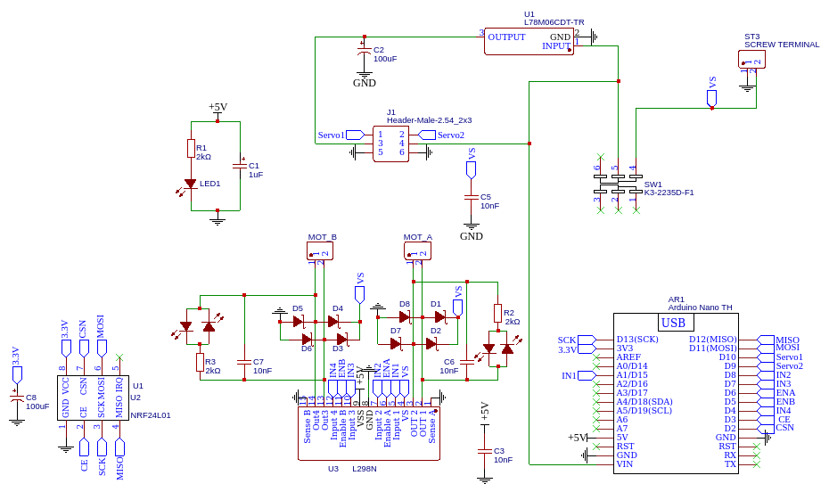
I find that there’s not a whole lot of off the shelf options out there when it comes to remote controls with a dual H bridge for differential steering. This receiver is designed to fill that niche. I think it’s well suited towards combat robotics. The code does have a fail-safe that shuts off the motors if communication from the remote control is lost. I designed it to be as compact as possible, so it does require a few surface mount parts. There are 4 LED’s to provide a visual status of the H bridge. The battery and motors can be connected by screw terminal or soldered directly to the PCB to save some weight or space. The power switch does not disconnect power from the H Bridge. If you’re going to use this controller in combat robotics you’ll need to add an external power switch. There’s a pin header to connect a servo motor. If you’re trying to power a servo from the 5V on an Arduino you’ll find that you’ll quickly release the Arduino’s magic smoke. To solve this problem, there’s an internal L7806 voltage regulator just to power a servo motor. If you don’t need a servo, you can skip this L7806. There’s a small .01μF cap across each motor output to absorb the high frequency back EMF noise from the motors. It’s a good idea to also use a ferrite bead around the motor leads to prevent this noise from ever reaching the receiver/H-Bridge PCB.
Receiver Firmware
Receiver PNG schematic for easy viewing:
Easy EDA Schematic
EasyEDA PCB
Recever BOM